Yamaha 33 Electrical Upgrade
When I purchased Tosca in Fall of 2018, I knew that I would have to do some work on the electrical system, The previous owner had already invested heavily in some nice goodies like a new mainsail, chartplotter, radar and instruments, but the survey found some unsavory wiring and to be honest, I was surprised that the insurance company didn’t squawk. In retrospect, I think this was typical for a boat this age. At the time I was concerned, but not alarmed.
 |  |  |  |
 |  |  |
Since the insurance company didn’t squawk, I focused on the other items called out in the survey (and some that were discovered after the fact) and shelved the electrical work for later.
I got the rig surveyed after the purchase (dumb) and it was deemed to be in poor condition. I had the late, great Brion Toss work up the rigging while I rewired the mast, with new LED steaming/deck light, anchor light and VHF antenna. Oh, and the chainplates were corroded. 4 new chainplates were fabbed and polished. Gah. The aluminum halyard organizer at the base of the mast needed welding and one of the sheave holders was missing. It was a lot of money and after almost 8 months of ownership I still hadn’t sailed anywhere. So far, Tosca left me a bit bruised and a lot poorer.
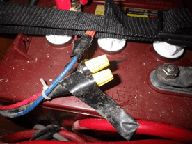
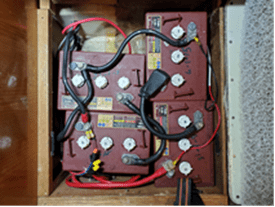
A bit of good news arrived in the inbox, December 2018. I was the lucky winner of a Firefly Group 31 battery on the Cruisers Forum giveaway. Hooray! Wait, Tosca didn’t really need new batteries. The owner previous to the one I purchased her from had installed 4 Trojan T-125’s in one of the storage compartments. This provided quite a bit of juice, but the boat wasn’t designed for that kind of weight and she had a noticeable list to port. Plus the batteries were in no way contained, and I was again surprised that the insurance company didn’t raise an objection. Or maybe they were just going to deny the claim later. Who knows what goes on in their evil hearts.
Alas, what Lady Luck giveth, Lady Luck taketh away. Or something to that effect. In January of 2019 I noticed that the Ample Power battery monitor was no longer monitoring. Ample Power made good gear in their day, and the owner was known for his scientific and fact-based approach to the care and feeding of lead acid batteries. Unfortunately, 8 bells rang for the owner and the company was no long in business. Well OK, time to look into alternatives.
Tosca also had an Ample Power alternator and voltage regulator. The schematics were helpful if you were an EE.
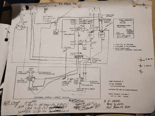
I’m not. The battery monitor and the voltage regulator were tied together, I think. Like I said, I’m not an EE. I wasn’t sure that one would operate without the other. Nor was I sure that damage would not occur if I tried. So I added a voltage regulator to the shopping list.
I started researching marine electrical systems. Sites like Marinehowto.com and Stu Jackson’s Electrical 101 links on the forums were invaluable. I read Nigel Calder’s book, which I already had, and also bought Charlie Wing’s book.
Just to complicate matters further, I peeked down the lithium battery rabbit hole. That’s a scary place. I already had a steep learning curve ahead of me and thought that if I went that route, and it went badly, it might be a lot more expensive than the route I was planning. So I saved LiFePO4 for another boat.
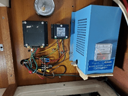
The remaining piece of the puzzle was the inverter/charger. The Heart Freedom 10 was somewhat precariously installed above the quarterberth. The flex in the overhead was pretty questionable. It had been there a while, but that didn’t mean it wouldn’t change its mind, likely at the worst possible moment. The unit is an older one, and didn’t have a lot of flexibility in the charging programs. The Firefly batteries needed a charging scheme that the Freedom 10 couldn’t provide. So another component was added to the list.
How Much Power?
With the choice of batteries already made, I then needed to figure out how many of them I would need and could fit. With the help of resources on several forums, Bluesea.com, emarinesystems.com and others, I worked up an electrical budget.
I estimated scenarios for at anchor, under sail during the day, under sail at night, and at the dock for reference. Claire and I both work from our laptops, so I estimated about 90 AH for a 24 hour period at anchor. If we want to stay at anchor without running the engine, I'd need about 90 AH of capacity at worst. Each Firefly provides 92 AH capacity at 80% DoD, in the best case scenario. Two would be needed at minimum. That’s cutting it close, so an additional battery will be needed eventually.
The Yamaha 33 is a wonderful boat and fun to sail, but it does not have ample storage. It’s a racer/cruiser, with more emphasis on the racer. The lack of storage also applies to locating the batteries. I’ve seen them installed in multiple places, but mostly under the settees. As mentioned, the PO installed 4 Trojan T-125’s in Tosca, but there was no containment for an acid spill. Moving to an AGM battery would eliminate this requirement. The issue with locating them under the settee is that the round trip cable run ends up being 30 feet or more, by the time the alternator and charger feed the batteries and the batteries feed the DC panel. This is murder on voltage drop, requiring larger diameter cables, larger terminals, more linear feet of cable and of course, more boat units. The settee compartments are also off the centerline , throwing the boat off balance. Tosca also had her inverter/charger installed pretty far off the centerline, on the same side as the batteries. Oh, the water tank is on the port side as well. She should have been named Eileen.
I measured the existing battery compartment, and of course there was plenty of room for two batteries. Not so for three.
 |
I initially though I would put the batteries under the cockpit floor, next to the quarterberth. Here’s a photo with the mock up batteries. The ones on the right are scaled to match 4 300A Winston LiFeYPO4 batteries.
That didn’t leave much room for the rest of the gear, which would include the inverter, galvanic isolator and voltage regulator. After much head-scratching, I drew up a solution that located them next to the engine compartment, under the quarterberth. I attempted to draw it 3 dimensions so I could check fit before committing.
 |
I should mention that I live 600 miles away from the boat, so any fabrication takes some careful measurement and a carload of tools to fit things once back at the boat.
Although I’m jumping ahead here, that location worked out pretty well. There's just enough room to remove the engine cover, and once off maintenance access is not bad. There's also room for a third battery with a little fabrication. The batteries are closer to the centerline. A win.
Charge It!
Relocating the batteries, it turned out, was the easy part. Deciding on how to keep them charged was far more complicated. The original house bank of 4 Trojan T-125’s was charged by a Heart Interface Freedom 10. The HIF10 was good for about 50 amps of charging. This was sufficient for charging from shore power and the 1,000 watt inverter capacity was adequate for the expected inverter load. The start battery was charged by a Guest 120v charger at the dock and a West Marine battery isolator/combiner.
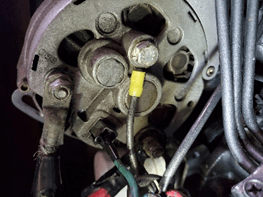
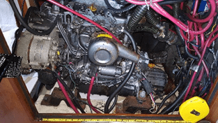
The alternator was a 106 amp from Ample Power, driven by a single v-belt, externally regulated by an Ample Power #1021-A 3 step regulator. The rating is hand-written on the alternator. Maybe they tested it prior to delivery? Belt dust was minimal but I hadn’t done a lot of charging with the engine. The boat was repowered about 20 years ago. I suspect that’s when the alternator and voltage regulator were installed. My understanding of the Ample Power equipment is that it was ahead of its time 30 years ago, but it’s no longer supported. The alternator seemed to be performing well, and the plan was to trust it until proven otherwise.
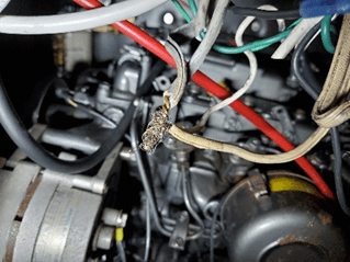
Adding to the confusion was the fact that the wiring was a mess. While all the ground wires came to a single distribution point, that point was a single stud attached to the firewall in the engine compartment that every ground was bolted to. I think there were 6 lugs stacked on the stud. The house bank was fused, but at the wrong end of the wire. The 480 AH bank was fused with a 200A ANL fuse, which in retrospect was probably correct due to the undersized wiring. The 3 conductor solid wire for AC power (on the right in the photo) was the wrong type for the application. And so on.
The initial plan was to:
- Rewire. Starting with the battery compartment, replace everything between the batteries and the engine. Bring the boat up to ABYC spec.
- Replace battery monitor. Leaning towards the Balmar SG-200, but if I went with the Victron inverter/charger, then that might change.
- Replace the voltage regulator with a Wakespeed 500 or Balmar MC-614.
- Install an ACR-SI to charge the start battery in tandem as needed.
- Install manual switching to turn the start battery into an emergency reserve for the house bank, and be able to start the engine from the house bank if needed.
This is where I started considering LiFeYPO. Expensive and more complex, but very tempting in terms of space and weight. Lithium was not optimal for the current use case but would be as we spent more time away from the dock.
These requirements pointed to a new charger, ideally one that could charge FLA, AGM or LiFePO4 chemistries.
LiFePO4 has its own unique installation requirements. I won’t go into the details here, as there are plenty of excellent resources on the web to help with that decision. A LiFePO4 installation seems to work better when designed with a separate inverter and charger, to separate the charge and load busses. There are plenty of examples of this not being a requirement, but my reading seemed to indicate good reason for including this in the design. This meant more space needed, and more money than a combined inverter/charger. Add in the high cost of the batteries, while also looking at a total rewiring job and this pretty much killed the lithium path for me. For now, at least.
I looked at the Xantrex, but the service issues pointed me elsewhere. The Mastervolt equipment looked good. Then I checked out the Victron gear. Since I’m far from the boat, the built in remote monitoring was a strong plus. The equipment looked well engineered and Victron had a really good reputation. Their software is somewhat open-source, which appeals to the tinkerer in me. I started incorporating the Multiplus 3000 into the design. The downside was that it was way more inverter than we needed, and the distance to the battery compartment is 30+ feet as the wire snakes, requiring 4/0 cables to carry the current and minimize voltage drop. This was excessive for a 33’ boat. The main advantage was that they are highly programmable and can integrate with a lithium BMS should I ever go there. It also fit in the available space. More research indicated that the compact 12/2000 would also work, meet the space and power needs and was a bit less expensive as well. Decision made.
Next: 10lbs of gear in a 5 lb suitcase.